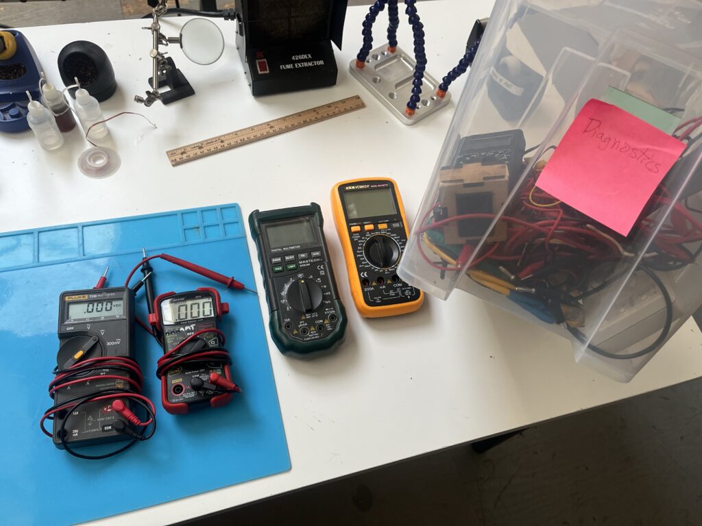
Multimeters can help diagnose and reveal the state and condition of many electrical components and circuits. They can help you determine the presence or absence of electrical activity in parts of circuits you may build, and can measure the strength (voltage) and amount (current) of electricity. They can also help you determine whether components are electrically connected, and they can help you measure how much some components impede or permit the flow of electricity (resistance).
Multimeters may have visual indicators in the form of digital LCD screens or, more traditionally, needle gauges. They may also have audio beep or tone indicators for some tests, particularly connectivity tests. Most require batteries to operate.
Most feature a pair of electrical wire leads for connecting the multimeter to whatever you are testing. In most units, each lead can be unplugged from the multimeter. Traditionally, one is colored black (a convention for ground) and the other red (for positive), but they are not functionally different; each is simply a wire, usually with a pointy tip.
Multimeters usually have dials and/or buttons used to configure the mode and scale of measurement. For a given circuit you may be testing, there may be combinations of multimeter configurations and circuit test locations (i.e., where in your circuit you touch the multimeter test leads) that could damage the multimeter or your circuit. Informed and intentional use is likely to yield best results.
This WikiHow page has text and illustrations describing some ways to use a digital multimeter.
ACE Electronics has a number of multimeters in a bin labeled “Diagnostics.”

