Steward: None. We no longer have this at AMT.
Asset Number: AMT038
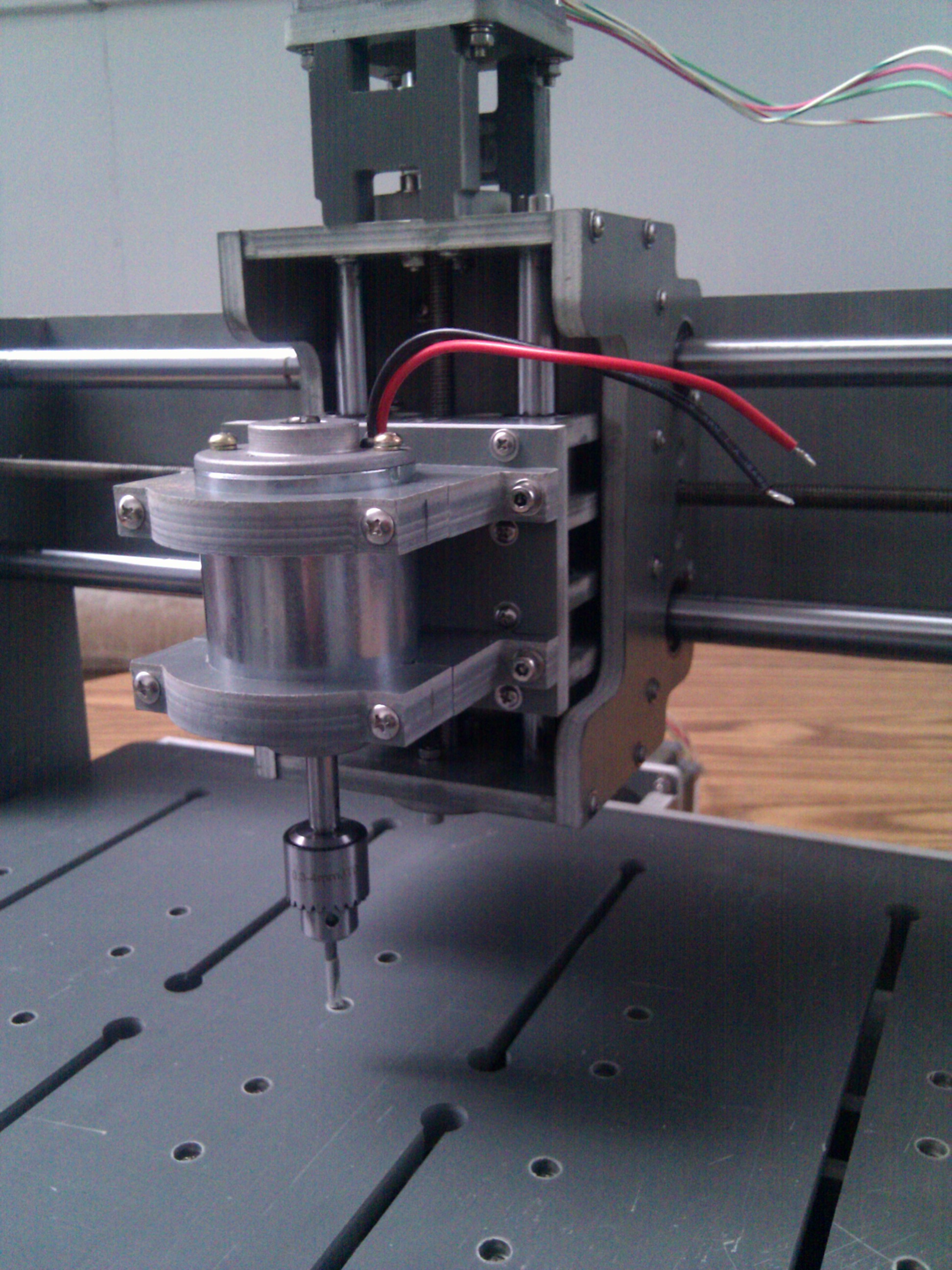
CNC engraving/mill by Zen Toolworks aka Guido
Photos

Useful info
Guido is his nickname and engraving’s his game.
Currently, this CNC beast is equipped with a 3mm 30degree V-shape bit, meant for engraving. Other bits can be used up to a shank diameter of 4mm with the current drill chuck.
It uses a power supply of 12V and up to 15A for both steppers and spindle, but this may change.
Guido is now downstairs, next to Chip (the big CNC)
In order to hook Guido’s enclosure up to the dust collector and more or less put all of our messy tools in the same place, Guido has been relocated to the table next to the big CNC.
The old Guido laptop has been left behind and Guido is hooked up to the Mach3 installation on the same machine driving the big CNC. If we ever run into the situation where folks want to use Guido and Chip at the same time then we should resurrect some garbage PC to drive Guido.
There is a DB25 A/B switch between Guido, Chip, and the CNC computer. ”’Set the switch to ‘B’ to use Guido!”’
Launch Mach 3 on the PC and select the ‘Guido’ configuration.
NB: There is a wacky custom DB25F-DB25M cable connected to Guido that swaps some of the pins around to deal with modern parallel ports. Don’t bother trying to use that cable on anything else because you will be disappointed.
”’NB: Guido is usable! (though not perfect)”’. See the list of remaining tasks later in this page.
Configuration Settings
To cope with a reluctant parallel port, the Z+Y enable pins are tied together in a custom cable and host pin 2 is used to drive the X step pin on pin 1 of the motor controller connector.
{| width=”75%” cellspacing=”1″ cellpadding=”1″ border=”1″
|+ Mach 3 Pin Settings for Custom Cable
|-
! scope=”col” | Name
! scope=”col” | Host Pin
! scope=”col” | Motor Controller Pin
|-
| X Step
| 2
| 1
|-
| X Direction
| 7
| 7
|-
| Y Step
| 8
| 8
|-
| Y Direction
| 3
| 3
|-
| Z Step
| 5
| 5
|-
| Z Direction
| 4
| 4
|-
| Z +Y Enable
| 6
| 6 and 2
|-
| X Enable
| 14
| 14
|-
| Spindle Enable
| 9
| 9
|-
| Limit
| 13
| 13
|-
| E-Stop
| 12
| 12
|-
| Probe
| 10
| 10
|}
Mach3 Settings
I’ve never actually tried grbl with Guido, but using the grbl settings in mach3 gave very very wrong results.
based on wild guessing, i used these settings in mach3 and things seem OK:
Steps per mm (all axes): 400
Max velocity: 1280mm/min
”’grbl settings for Zen Toolworks controller board”’
Steps per mm (all axes) – 1280
mm/revolution – ?
steps per revolution – ?
micro-steps –
default velocity – 400mm/min
acceleration – ? mm/sec^2
{| width=”600″ cellspacing=”1″ cellpadding=”1″ border=”1″ align=”center”
|+ Connections between DB25 connector for controller board and Arduino running GRBL
|-
! scope=”col” | CNC Driver
! scope=”col” | Name
! scope=”col” | GRBL/Arduino
|-
| pin 1
| X Step
| D2
|-
| pin 7
| X Direction
| D5
|-
| pin 14
| X Enable
| D8*
|-
| pin 8
| Y Step
| D3
|-
| pin 3
| Y Direction
| D6
|-
| pin 2
| Y Enable
| D8*
|-
| pin 5
| Z Step
| D4
|-
| pin 4
| Z Direction
| D7
|-
| pin 6
| Z Enable
| D8*
|-
| pin 9
| Spindle Enable
| D12
|-
| pins 18-25
| GND
| Arduino GND**
|}
Notes:
”*” as of 12July2012, all three axis enables are wired together to a single Arduino pin. In the future these connections might be split to provide improved safety/control/monitoring, particularly once limit/home switches are in place. For example, the enable could be wired to LEDs to signal axis activity.
”**” 14July2012, Confirmed controller board DB25 shorts pins 18-25 and connects to 5V GND. Added additional wire to Arduino shield connecting pin 25 to Arduino GND.
Prototype GRBL Shield using the above pinouts
[[File:GRBL shield-proto1.jpg|Top]][[File:GRBL shield-proto1b.jpg|Bottom]]
Pin 1 of the molex connector is top-right. ”’The cable should to be plugged in with the red stripe to the right.”’
GRBL Firmware
[[Media:Guidofirmware2012Jul12.bin]] (file missing link needs to be found if valuable)
DaveR made a few changes to support the controller board we’re using. One change is enables are active low. This is implemented as an IFDEF in the sources. The pinouts are changed to reflect the above table in config.h. ””’DaveR, please add any additional changes you can recall””’.
Github sources: [http://github.com/davr/grbl http://github.com/davr/grbl]
How to make a CAD design AND machine it on Guido
- Best open source tool for designing I have found so far is HeeksCAD (thanks Andreas!!; I really need to contribute to [http://heeks.net/ HeeksCAD project], it is awesome!). It very simple to use and has a CNC plugin called HeeksCNC. It is currently installed and running on the same laptop that controls Guido.
- Create your design. If you are going to machine something, keep in mind that the milling only happens by moving the Z axis up and down, so anything that cannot be bored out by this action, cannot be machined on Guido. When creating your design, make sure you place it in the positive XYZ directions, as this will be critical once EMC2 takes over the gcode.
- I will post a brief tutorial on using HeeksCAD/CNC and EMC2 in combination for our specific setup and Guido’s various tooling as soon as I figure it out myself. But in the meantime, check out these HeeksCAD tutorials (they are aimed at rep-rap machines, but CNC will be very similar) to get an idea of how it works: http://www.youtube.com/watch?v=idV54AqNbPo
- Once a design is created, HeeksCNC plugin will render the gcode necessary to send to EMC2. This happens from the machining toolbar, “post-process”. It will output a file that contains some special characters that need to be removed along with the initialization sequence (I have not set it up for Guido specifically just yet, so these are not pertinent here)
- Load the .nc (or .ngc) file into EMC2 and you shall see the toolpath that you just created in HeeksCAD on the screen. If all is set up in EMC2, just hit play and watch it go.
If you’re interested in making circuit boards with Guido, check out [[Milling_Circuit_Boards|Milling_Circuit_Boards]].
Investigation
”’Laptop works, needs power supply”’
The laptop connected to Guido has a bad power supply. If anyone has a Dell laptop power supply that will fit an older Inspiron 8200 we can get this running quickly. I charged the battery in the laptop and was able to power it on along with the CNC machine. If we can’t get a power supply for this laptop we need to get a new control pc/laptop with a parallel port.
”’CNC machine works, needs DB25 cable”’
After confirming the controller board is optoisolated, I powered up the machine. The DB25 cable used with Guido seems to have moved elsewhere so I borrowed the one off the large CNC downstairs and was able to power up the machine, connect to the laptop, move all x/y/z axis to the limits and software control the spindle. It looks like the failure was isolated to the laptop.
”’Laptop specs”’: Dell inspiron 8200, Ubuntu 10.04, emc2 2.4.6
”’laptop login”’: amt/(wifi password)
”’controller specs”’: board has “www.hyu68.com” stenciled. 3 driver ICs are toshiba TB6560AHQ. [http://forums.zentoolworks.com/viewtopic.php?f=11&t=11 A post on zentoolworks.com forum]
[http://wiki.acemonstertoys.org/images/8/80/HY-TB3DV-M_3Axis_Driver.pdf ”’Controller manual”’]:
”’Controller Schematic”’
Some nice person reverse engineered the cheeseball stepper controller and made a schematic for it. You can find it here: [http://www.drkfs.net/REVERSESTEPPER.htm ”’Controller Schematic”’].
Repairs
Labelled and reconnected screw terminals
I noticed the screw terminals had some loose connections. On the Z axis the machine wasn’t moving smoothly because one of the stepper wires was intermittently connected. I reconnected all the wires to the terminals and labelled them.
”’TASKS REMAINING:”’
*Remount controller board and spindle controller to the machine. Preferably, enclose them in a case to prevent dust and protect them from hands.
*Make an enclosure. If we mill PCBs we want some sort of an acrylic enclosure to keep the fiberglass dust contained.
*Make some holddowns. Preferably ones that can accommodate a small standard sized PCB. (the bed is slotted to accept M6 hex head bolts. like any good standard, these come in different sizes but the bolts from Cole Hardware on 4th St in SF seem to fit. I’ll be making a PCB holder/spoil board using some of these bolts).
*Get bits. We only have a couple bits.
*Make electronic homing. I have some ideas I want to investigate.
*The chuck key is missing. Zen toolworks doesn’t even ship this chuck anymore.. it’s a ‘Chumpower JT0’ and my guess is that it’s compatible with a Jacobs K0 key which i have ordered. Stand by.
*The X axis is no longer working. My guess is that parallel port pin 1 behaves differently in SPP vs ECP vs EPP mode on different PCs. We may be able to fix this by messing with the CNC PCs BIOS settings or by hacking up a connector to use something other than pin 1 for the X axis (maybe pin 16 or 17). Hacking up a connector would have the added benefit of giving us a place to plug in all of those dangling limit switches.Pin 16 and 17 don’t work any better. The hacked up connector could combine the motor enables, freeing up two of pins 14, 6 and 2.
*There is no need to break out pins for the limit switches since they are already opto-isolated on the driver board and connected to pins 10, 11, 12 and 13 of the DB25.
*re-wire the limit switches so they are all normally closed and in a series and then connect them to one of the four inputs on the driver board
*add 3 more limit switches, one for the other side of each axis
*add an e-stop switch
*put the spindle speed and direction control in a conveniently located box with the e-stop switch
*calibrate the steppers in Mach3
*Verify that steps/mm is set correctly using some measuring tool that is more accurate than the metal ruler that i used to set the value.
*set the soft limits in mach3
*It’s entirely possible that I’ve used inappropriate wire to relocate the spindle controls–the wires to the speed pot may be too small.
Software Links
[http://www.shapeoko.com/wiki/index.php/Advanced_Software Shapeoko wiki]
[http://www.shapeoko.com/wiki/index.php/Grbl_Controller Grbl Controller] – [https://github.com/kosme/GrblHoming/downloads download] — Windows & Linux. Works, but only after I remapped my com port (the UI only lets you pick COM1-COM16)
[https://github.com/nm156/CNCInfusion CNCInfusion] — C# based, probably Windows only. Needs compiling
[https://github.com/synthetos/tgFX TinyG GUI tgFX (might work for grbl)] — Java/JavaFX based. Would not start for me.
[https://github.com/Highlander01/PythonCNCGUI-GRBL Python CNC GUI ](for a modified version of grbl?) — Python based, docs say works well in linux, and slowly in windows.
[[Category:Equipment]][[Category:CNC]]